Smart Traffic Light 2: Building the Prototype
Creating a miniature internet-enabled traffic light using an ESP-01s microcontroller.


Welcome back to our smart traffic light series! In the previous post, we set up an IoT network. Now, it’s time to bring our concept to life with a miniature internet enabled prototype.
Hardware
In the first part of this blogpost we will focus on the hardware of the project. This project is built around the ESP-01 microcontroller. The ESP-01 is a compact Wi-Fi module based on the ESP8266 chip, designed for IoT projects with built-in Wi-Fi capabilities. Unlike larger Arduino boards which offer more GPIO pins and features, the ESP-01 sacrifices some versatility for an extremely small form factor and lower power consumption, making it ideal for simple, space-constrained IoT applications like our mini traffic light.
Components
These are the parts I used:
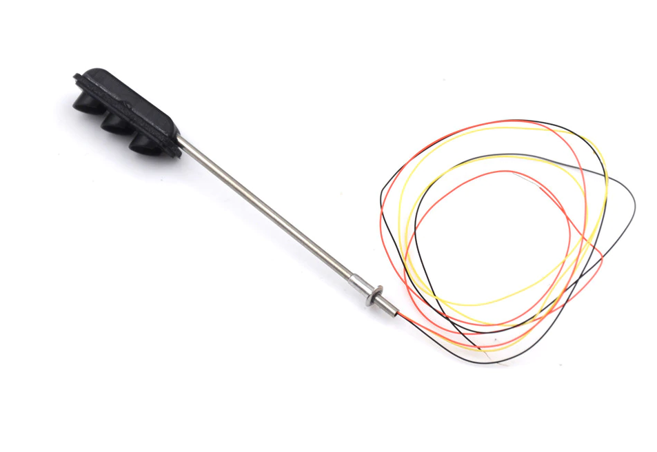
- 1x Miniature Traffic Light
- 1x ESP-01s
- 1x Power Cable with Switch
- 1x 5V to 3.3V Stepdown Converter
- 1x Plastic Case (48 * 26 * 15 mm)
In order to program the ESP-01s you also need an adapter. It is also possible to use whatever microcontroller with a connection to the internet.
Power
Our micocontroller runs on 3.3V. Luckily, the LED’s on our miniature traffic light also run without anny hassle on this voltage, so there is no need for resistors. These LED’s can be directly powered by the ESP-01 as they consume very little power.
I wanted the whole thing to be powered through a USB cable. Phone chargers and USB ports produce 5V so we need to step that down to 3.3V. I used a small DC-DC buck converter I had lying around. Most converters will be able to do the job, as the whole circuit will only consume ~250mA at max.1
Assembly
There it is, fresh from its journey across the seas! This is a common cathode circuit, which means that the shared wire (the black one) has the positive polarity (+3.3V). The GPIOs now function as a sink: when a pin is pulled down to 0V, a current will flow through the LED to the pin. It may be a bit counterintuitive at first, but when we pull a pin LOW, the LED will turn on.
Assembling our traffic light is straightforward:
- Drill a hole in the plastic case for our traffic light and its wires to go through
- Solder the components onto a piece of perf board, following the wiring diagram in Figure 2
It doesn’t really matter to which of the four GPIO’s (IO0, IO2, RXD, TXD) you connect which LED. This can all be adjusted later programmatically anyway!

I didn’t make it easy by choosing such a small plastic case. It can be really hard to fit all components in. I used bits of kneading glue to sort of fix the board and the traffic light to the case. Furthermore the traffic light comes with extremely thin wire. You can strip this wire using a soldering iron. It might be hard at first to handle these tiny components.
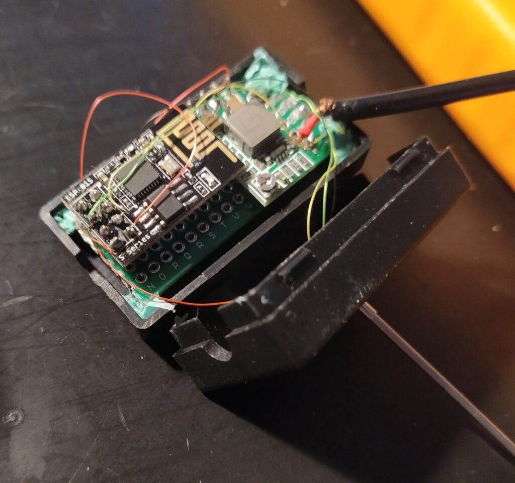
In the figure above you can see all of the components wired up together. The USB cable in this picture looks a bit loose. That’s the case because I took this photo while repairing that connection.
Software
Now for the fun part – programming our traffic light! Here’s what we want it to do:
- Connect to WiFi
- Connect to our MQTT server
- Publish its status in the topic
connection/mini-stoplicht - React to changes in
vvb/status - Display inbuilt animations
The full source code for driving the miniature traffic light is available on GitHub.
Control the Lights
How to control the lights programmatically? Since we have a common cathode circuit, we’ll have to turn the pins to 0V for our LEDs to turn on. You first have to declare the pins and then set them to OUTPUT to be able to control them. The setup method will be called once upon start.
// According to our wiring diagram
const int PIN_RED = 3;
const int PIN_ORANGE = 0;
const int PIN_GREEN = 2;

void setup {
  pinMode(PIN_GREEN, OUTPUT);
  pinMode(PIN_ORANGE, OUTPUT);
  pinMode(PIN_RED, OUTPUT);
}
Now turning an LED on or off goes like this:
digitalWrite(PIN_RED, LOW);    // Turn ON
digitalWrite(PIN_RED, HIGH);   // Turn OFF
WiFi
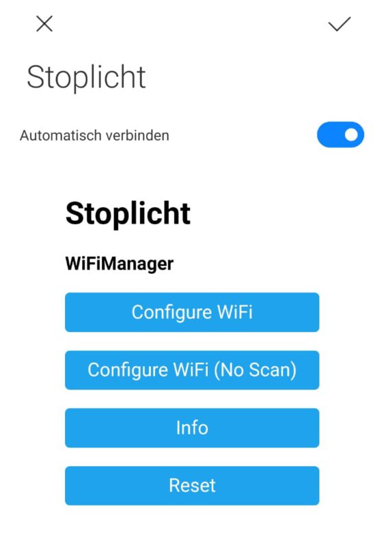
We want our traffic light to work anywhere, so hard-coding WiFi credentials is a no-go. Luckily, there exists a library to handle this exact problem: WiFiManager. That works with the standard ESP8266WiFi library. This neat library creates an access point with a captive portal, allowing users to select their network (see Figure 4). It’s like giving your traffic light its own tiny smartphone setup screen! If you add your details, those are saved into PROGMEM. So even if you restart your device, it will still remember your SSID/password.
The library also makes it easy to add custom HTML. I added a custom footer that contains my contact information.
  WiFiManager wifiManager;
  WiFiManagerParameter custom_text("<p>(c) 2019 by <a href=\"mailto:...\">Jos Zuijderwijk</a></p>");
  wifiManager.addParameter(&custom_text);
MQTT
For the MQTT connection I used the PubSubClient library. You just provide your MQTT details (host, user, password, port) and this library will do the rest. This piece of code connects to the broker, and takes a so-called will message. This message will be sent to the broker if the device suddenly disconnects. The will message I provided is a retained ”0” in topic connection/mini-stoplicht. After first connecting the client will publish a retained “1” in the same topic. This way we can easily see if the device is connected or not. I also let the client subscribe to the vvb/status topic. That’s the channel the commands will be sent to.
WiFiClient wifiClient;               // WiFi
PubSubClient client(wifiClient);     // MQTT

if (client.connect(mqtt_client_name, mqtt_username, mqtt_password, "connection/mini-stoplicht", 0, 1, "0")) {
      // Send Hello World!
      client.publish("connection/mini-stoplicht", "1", 1);
      client.subscribe("vvb/status");
}
The MQTT callback function, that is the function that is called whenever a message is published to a topic that the client has subscribed to, looks like this.
void callback(char* topic, byte* payload, unsigned int len) {
    String msg = ""; // payload
    for (int i = 0; i < len; i++) {
      msg += ((char)payload[i]);
    }

  if ( strcmp(topic, "vvb/status") == 0 ){
    if (msg == "0"){
      updateLights(true, false, false);
    } else if (msg == "1"){
      updateLights(false, true, false);
    } else if (msg == "2"){
      updateLights(false, false, true);
    }
  }
}
This will check if the topic name equals to the value we expect (more useful when subscribed to more than one topic). Then it will set the lights using the helper function updateLights, according to the received value. This function takes three booleans, each representing an LED of the traffic light that is either on or off.
User feedback: animations
Now the device basically does what we need. But it’s not user friendly yet. How is a user going to know if the traffic light is not able to connect to the WiFi network? Okay, someone could check if the captive portal is up, but there is no visual indication.
One way to solve this is adding animations. If the traffic light is connecting to the WiFi network I want it to go from green-orange-red every 500 milliseconds. If the traffic light has failed to connect, I want the red light to blink every second. The easiest way to implement this is using a Ticker, which is a standard library for Arduino. A Ticker executes a given method repeatedly without using the blocking delay() function.
I implemented the animations like this:
int animationCycle = 0;

// connecting to wifi animation
void startupAnimation(){
    if (animationCycle == 0){
      updateLights(false, false, true);
      animationCycle++;
    } else if (animationCycle == 1){
      updateLights(false, true, false);
      animationCycle++;
    } else if (animationCycle == 2){
      updateLights(true, false, false);
      animationCycle++;
    } else if (animationCycle == 3){
      updateLights(false, false, false);
      animationCycle = 0;
    }
}

// access point animation
void apAnimation(){
  if (animationCycle == 0){
    updateLights(true, false, false);
    animationCycle++;
  }else{
    updateLights(false, false, false);
    animationCycle = 0;
  }
}
We then can attach the animation functions to the ticker with a certain interval so it gets called repeatedly.
Result
The traffic light responds perfectly to the MQTT messages that are sent in the vvb/status topic. You can easily test that using software like MQTT Explorer. In Figure 5 you will see the animation for “there is no internet connection, an access point has been made” and “trying to connect”.
A future improvement could be switching to an encrypted MQTT connection.
In the next and final post we will create a full-fledged internet controlled traffic light.
-
The ESP-01 consumes 200mA at maximum power (e.g. while connecting to the internet) according to the datasheet and a typical LED consumes around 20mA. ↩